Application study of silicon impression material for reducing metal artifacts: preliminary study for head and neck cancer radiotherapy
Article information

Abstract
Metal artifacts cause inaccuracies in target delineation, radiation treatment planning, and delivery when computed tomography images of a radiotherapy patient implanted with a high-density material in the body are acquired. In this study, we investigated the possibility of obtaining improved images in clinical trials through metal artifact reduction using silicon impression materials without the need for a specific metal artifact reduction algorithm. A silicon impression material exhibiting a constant Hounsfield unit (HU) value according to the mixing ratio of the catalysts and bases was selected. The material did not exhibit any change in weight or shape over time. For both the instances of inserting the metal material and applying the silicon impression material, the HU value and dose were compared with homogeneous cases filled with waterequivalent materials. When the silicon impression material was applied to the region where the high-density material was located, the HU value was within 5% and the dose was within 3% compared with those of the homogeneous cases. In this study, the silicon impression materials reduced metal artifacts. However, because the composition, shape, size, and location of high-density materials differ, further studies are required to consider these factors in clinical applications.
INTRODUCTION
Because head and neck cancer has a complex anatomical structure, accurate delineation of tumors and normal tissues is important to increase the effectiveness of radiation therapy. However, some patients have metal substances inserted in the head and neck owing to implant surgery and orthodontics due to aging and for cosmetic effects. During computed tomography (CT) simulations for radiation therapy, the metallic material in the oral cavity causes streaks and blurring artifacts, resulting in unclear tissue contours and deterioration of the accuracy of radiotherapy plans for dose distribution [1-3]. In addition, because the exact CT number for the metal material included in the CT image is not considered, side effects such as necrosis may occur in normal organs owing to inaccuracy in the dose distribution [4,5]. The physical characteristics of radiation caused by metal material insertion tend to increase the dose on the side where the tissue and metal material are adjacent [6,7]. Therefore, in radiation therapy for patients with head and neck cancer, artifact reduction of images by metallic materials and alignment of accurate Hounsfield units (HUs) are very important for the accurate definition of treatment sites and for a clear distinction between tissue and metallic materials. In this study, the material used as a metal artifact shielding material was a silicon impression material, which is widely used in dentistry and orthodontics. It is harmless to the patient’s body and can float according to the tooth structure. Metal artifact shielding materials are sometimes used to fix the tongue during radiation therapy for head and neck cancer; however, they have never been used for metal shielding purposes. The application of a metal artifact shielding material is expected to enable a clear distinction between tissues through accurate HU assignment of the metal density and the surrounding tissues, rather than overriding any HU, such as water, in the radiation treatment plan.
This preliminary study aimed to determine the effects of dental materials on clinical usability.
METHODS
1. Selection of dental impression material
Silicon impression materials mixed with catalysts and bases were tested. One impression material with a relatively constant HU value was selected from the silicon impression materials produced by five different companies, even when the mixing ratio of the catalyst and base was changed. The HU value of the five different silicon materials was measured by varying the catalyst and base ratio under the same CT imaging conditions at 120 kV, 300 mAs, and 3 mm slice thickness (Brilliance CT Big Bore; Philips Medical Systems, Cleveland, OH, USA), and it was verified that the fifth silicon material had a constant HU value regardless of the mixing ratio. The fifth silicon material with an average HU of 789.1 (standard deviation [SD], ±9.37; HUmin, 968.4; HUmax, 800.4) was selected for this study, as shown in Figure 1. Subsequently, a phantom was created based on the weight of the selected material and monitored for approximately 30 days.

The HU results of five silicon impressions according to the mixing ratio of catalyst and base (C [%]/B [%]). HU: Hounsfield unit, SD: standard deviation.
2. Evaluation of HU
The HU effect of the silicon impression material was confirmed by using a solid water phantom inserted with a titanium bar. Phantom images were obtained under the same conditions as when the silicon material was selected. The EclipseTM treatment planning system (Varian Medical System, Palo Alto, CA, USA) was used for analysis. Figure 2 shows the phantom setup for HU evaluation: (A) homogeneous, (B) inhomogeneous with titanium metal insertion, and (C) metal artifact reduction with a silicon impression material. For the four regions, the HU values were compared with those of the titanium bars inserted for the homogeneous cases.

Evaluation of Hounsfield unit (HU) results in regions for (A) phantom, (B) homogeneous region, both inhomogeneous with a titanium bar, (C) without silicon impression material, and (D) with silicon impression material.
3. Evaluation of dose distribution
For dosimetric evaluation, EBT3 films (Ashland Specialty Ingredients G.P., Bridgewater, NJ, USA) were inserted.
(A) Case 1: cube phantom with water-, bone-, and lung-equivalent materials.
(B) Case 2: cube phantom with a titanium bar, and boneand lung-equivalent materials.
(C) Case 3: cube phantom with a titanium bar, bone- and lung-equivalent material, and silicon impression material.
The evaluation of all cases was based on homogeneous conditions, without any inhomogeneous material. The CT images for each case were acquired under the same conditions as those used in the HU verification experiments. Dose distributions were then calculated using the EclipseTM treatment planning system. The EBT3 films were scanned 24 hours after irradiation to allow polymerization to stabilize. Measured films were acquired in transmission mode using a flatbed scanner (EPSON Expression 10000XL; Seiko Corporation, Tokyo, Japan). Each film was read at a resolution of 150 dpi and saved as an uncompressed tagged image file.
The second case was tested using bone powder. As shown in Figure 3, the implant was inserted into a case filled with bone powder. Dose calculations were performed with a field size of 20×20 cm2, 6 MV energy, and a 3D-conformal four-portal (0º, 90º, 180º, and 270º); and radiation was delivered using Varian IX in the same manner as that indicated in the plans. The doses measured by the EBT3 films were compared for each dose during treatment planning. The profiles of both cases were evaluated using gamma evaluation with a threshold of 10% and gamma criteria of 1%/1 mm, 2%/2 mm, and 3%/3 mm.

The bone powder phantom with implant. (A) Insertion part with bone powder. (B) Phantom. (a) Means insertion.
RESULTS
To confirm reproducibility, the weight of the silicon material was measured daily for 30 days. In all cases, the weight (within 0.30 SD) was found to be constant (Table 1). The HU values of the average (SD), maximum, and minimum on selected silicon material were 789.1 (9.4), 800.4, and 768.4, respectively.
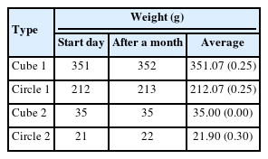
The weight constancy for the selected silicon impression materials
When applying a CT scan without a dental shield in a homogeneous case and a state in which a high-density material is inserted, the HU value tends to coincide with ±4.7% when the dental shield is applied in regions 3 and 4 (Table 2). There was a difference in the HU values for air regions 1 and 2 between the homogeneous and inhomogeneous cases. When only metal was inserted in the central area, the difference was 2.3%, and when shielding was performed, the degree of agreement was within 2%. At the film insertion line in the cube phantom, the distribution of the region close to the metal was representative. As a result of making a radiotherapy plan for homogeneous metal insertion and dental shielding and performing measurements using EBT3 film, calculations in the radiotherapy plan and film measurements tended to match when homogeneous and dental shields were applied. When the metal shield was not used, the center was less than 6%, and when the metal shield was used, the result was 1% lower (Fig. 4A, B). When the comparison between homogeneous and each inhomogeneous case, the lower gamma passing rate to metal insertion was shown as 58.47% at 1% and 1 mm criteria (Fig. 4C).
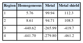
Comparison of Hounsfield unit (HU) results on homogeneous, metal insertion, and metal shield

Profile comparison on a homogeneous vs. (A) insertion of the titanium, and (B) the metal artifact reduction with impression material. (C) Shows the gamma passing rate.
In all cases, the planned and delivered distributions tended to be consistent within approximately 5%, but assuming that a uniform radiation distribution was delivered to the region of interest, the tendency of uneven radiation transfer by the metal is shown in Figure 5A-C. In addition, it was confirmed that the lowest gamma passing rate was shown for all gamma criteria when only the implant was inserted (Fig. 5D).
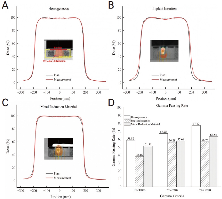
Profile comparison in the bone powder phantom for the treatment planning vs. (A) homogeneous, (B) insertion of the titanium, and (C) the metal artifact reduction with impression material. (D) Shows the gamma passing rates. The dose distribution for each case in the plan was 95% dose line.
DISCUSSION
The bone structural material used in dentistry was used to reproduce the density of teeth, and the phantom was reproduced by inserting the currently used implant. A method was proposed to make the control clearer during radiation treatment using the reproduced phantom.
The silicon material used for dental impressions has a disadvantage in that the exact composition of the material is not known because the composition ratio is not commercially disclosed. However, research has shown a metal artifact reduction effect when silicon materials are used. The difference was 16.1 HU on average with a standard deviation of 32.2 HU, the possibility of metal artifact reduction effect of silicon materials was shown in our study [8]. Moreover, Reitemeier et al. [9] and Chin et al. [4] reported that metallic dental materials with a high atomic number increase the backscatter of electrons for the energy used in radiation treatment, leading to an increase in oral mucositis. It has been reported that when a 3-4 mm thick material with a low atomic number is inserted between the oral mucosa and metallic dental material, the expression of mucositis is lowered by shielding against backscattering. The silicon impression material used in this study has a low atomic number of 14, effectively reducing the backscatter of electrons and mucositis. This study is needed because there is a limit to the direction in which the silicon impression material can be applied for shielding the head and neck implants, as the dose may vary depending on the irradiation direction of the photon [3]. Although in the case of hip replacement, the direction of radiation therapy can be adjusted during treatment, it is difficult to transmit radiation to avoid artificial tooth structures during head and neck radiation therapy. Photon absorption due to the high-density material contained in the oral cavity makes dose delivery inaccurate and produces over- and under-doses at the boundary between the organ of organ at risk and high-density material [10].
The degree of artifacts may vary depending on metal size, and because a high-density material is inserted in the oral cavity, the silicon impression cannot be applied in all directions. Further research on this topic is required. However, this study is meaningful because it shows that metal artifact reduction is possible without image correction through the application of equipment algorithms.
Acknowledgements
This study was funded by a research grant from Jeju National University Hospital in 2021 (202100270001).